It is the user’s responsibility to install the components in a suitable location. The S2K controller must be installed in a location that satisfies the following environmental conditions:
Atmosphere: The circuitry must not be exposed to any corrosive or conductive contaminants.
Ambient temperature:
0°C to +50°C (operating)
-40°C to 80°C (storage)
Note:
For UL approved installation of the following controllers, maximum ambient temperature is 40°C (104°F): IC800SSI216P2, IC800SSI216RP2, IC800SSI216D2, IC800SSI216RD2, IC800SSI228P2, IC800SSI228RP2, IC800SSI228D2, IC800SSI228RD2, IC800SSI407RS1, IC800SSI407RP2, IC800SSI407RD2, IC800SSI420RP2, IC800SSI420RD2.
Install the controller into ambient temperature conditions within the range of 0° C to +50° C. If the temperature exceeds this range, it may cause malfunction or damage to the controller. The controller heatsink and motor generate high temperatures. If the controller is housed in an enclosed control cabinet this heat load must be considered when evaluating the enclosure cooling requirements (see Section 3.1-Heat Load and Cooling for details on controller losses). Use heat exchangers or cooling devices to maintain an ambient temperature of 50° C or less.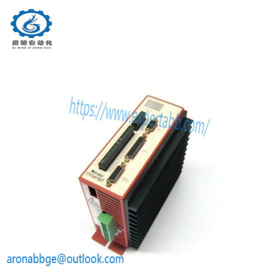
Humidity: 95% relative humidity or less (non-condensing)
Altitude: No more than 1,000m (3,300 ft) above sea level for full rating. Contact GE Fanuc Applications Engineering for derating at higher elevations.
Ventilation: This controller is designed for vertical installation to ensure proper cooling. Install the controller with sufficient space for ventilation. Avoid mounting wireways and other adjacent components too close to the heatsink, top or bottom of the controller.
Location: Keep the following location guidelines in mind when selecting a site for the controller:
Do not install in places with high temperature, high humidity, dust, dirt, conductive powder or particulate, combustible gasses, or metal chips.
Avoid places exposed to direct sunlight.
Mount only to noncombustible materials such as metal.
Do not stand/step on or put heavy articles on the controller or motor.
The controller housing is not a waterproof enclosure. Do not use outdoors or in any unprotected environment. The controllers are designed with open construction and must be installed in a closed electrical operating area i.e. an enclosure that protects personnel from contact with wiring terminals and provides a pollution degree 2 environment.
Avoid locations where there is exposure to radiation such as microwave, ultraviolet, laser light or X-rays.
Do not apply excessive stress, put heavy articles on, or pinch the cables.
Do not install the controller near heating elements such as cabinet heaters or large wire wound resistors. When such installation is unavoidable, provide a thermal shield between the servo controller and the heating elements.
Mount controller and other heat producing components higher in the enclosure to avoid overheating other sensitive electronics installed in the same cabinet.
Installing the Controller
The S2K Series controllers are designed for panel mounting in electrical enclosures designed for industrial applications. Enclosure cooling or ventilation must be adequate to maintain the ambient temperature to within the component’s specifications. Mount controllers vertically for proper cooling.
To ensure an adequate ground connection between the S2K and the panel to which it is mounted, install a star washer or equivalent under the mounting screws.
Firmly install the controller with screws and bolts without applying stress such as bending and twisting to the controller main unit.
Allow reasonable mounting clearance between adjacent units to ensure proper ventilation.
Since a misuse of the controller may lead to improper operation, or may damage the controller, carefully read the following cautions and warnings:
Be sure to ground the controller properly using the ground terminals on the power input connector. Proper grounding includes conforming to applicable national and local electrical codes.
Do not apply higher than rated voltage to the power input terminals (L1, L2 and L3)
Do not apply the main input power to terminals other than terminals L1, L2 and L3 or damage will occur. Refer to Section 3.6 for wiring information.
The power supply uses a capacitor filter. When you turn on power, a high charging current flows and you may see a large voltage drop. We recommend that you install line reactors to limit the charging current if this presents problems with other equipment on the machine.
Do not perform a dielectric strength test or megger test on the controller or damage may occur. (When you perform a dielectric strength test or megger test to an external circuit, please disconnect all terminals to the controller so that no test voltage is applied to the controller.)
If you use a ground fault breaker, use one rated for “Inverter,” to withstand high frequency leakage current. See table 2-3 for fuse specifications.
Use the motor and controllers only in the designated combinations (Table 1-1).
When transporting, use caution to prevent damage to the S2K components. Do not move or carry the controller by holding the cables.
Installing the Motor
The S-Series and MTR-Series servo motors are designed for either vertical or horizontal mounting and have a protection rating of IP65 (not including the connectors and shaft). The motors should be mounted in a location where the environmental conditions are within the specifications stated in Chapter 2. Use the following guidelines when mounting the motors:
• Observe the shaft radial and thrust load limits. Loads exceeding these limits will cause premature failure of the motor. Excessive belt tension could cause bearing or shaft failure.
• Be sure to ground the motor using the ground wire in the motor power cable.
• Ensure that the motor cables are free from excessive stress, stretching, pinching or bending.
• To avoid damage, do not carry a motor by holding the cables or shaft.
• Do not apply excessive axial force or impact loads when installing the motor coupling or shaft pulley, or the encoder may be damaged. See axial load limit ratings in Chapter 2.
• Install the motor in a location free from corrosive contaminants, dust, excessive water spray, or combustible gas.
• The shaft of the S-series servo motor is treated with grease (Shell Oil Alvania No. 2) for corrosion protection during storage. Consider the effect of the grease on any plastic parts that are mated with the shaft.
• The optional servo motor brake should be used for holding stationary loads only. Do not use this brake to stop a moving load, or reduced life or damage to the brake may occur. Apply this brake only after the motor is stopped.
Related product recommendations:
GE UR8HH
Fanuc A20B-2002-0310/03A
GE IC3600TUAA1
GE A16B-2200-0250
GE IS200TGNAH1AAA
GE IC695ALG728
GE IC830M7
GE IC694TBB032E
GE DS215TCDAG1BZZ01A/DS200TCDAG1BDB
Bently Nevada 330901-10-25-10-02-00
GE A06B-0317-B081
More…

Leave a comment
Your email address will not be published. Required fields are marked *